A full pump rebuild sounds intimidating until you’ve done one. In practice, it’s a sequence of straightforward steps performed in order, using parts that are designed specifically to be field-serviceable. Most contractors who attempt their first rebuild are surprised by how accessible the fluid section is once it’s off the machine.
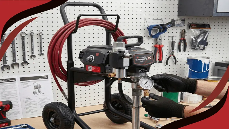
This walkthrough covers a complete rebuild of a Titan electric airless fluid section — packing, inlet valve, outlet valve, and piston rod inspection — using the Impact 440 as the reference model, though the sequence applies broadly across the Titan electric airless line.
Before You Start: Tools and Parts
You’ll need basic hand tools — adjustable wrenches, a packing removal tool (often included with repacking kits), a clean work surface, and the appropriate solvent for flushing. For parts, have on hand a complete repacking kit, an inlet valve assembly, and an outlet valve assembly before you begin. Starting a rebuild without confirmed parts on hand is the most common reason a one-hour job turns into a multi-day wait.
Confirm your exact model before ordering anything. The Titan 440 fluid section components are specific to that model — verify against the OEM diagram rather than assuming compatibility with a similar-looking machine.
Step 1: Relieve Pressure and Flush the System
Before any disassembly, relieve system pressure completely by triggering the gun into a waste container with the prime valve open. This is not optional — the fluid section operates at pressures that make skipping this step genuinely dangerous.
Flush the system thoroughly with the appropriate solvent until discharge runs clear. A clean fluid section is easier to work on and gives you an accurate read on component condition without dried material obscuring wear patterns.
Step 2: Remove the Fluid Section
Disconnect the suction tube and the high-pressure hose. Most Titan electric airless fluid sections detach from the main pump housing with a few bolts or a retaining mechanism specific to the model — consult your machine’s manual for the exact removal sequence, as this varies between model families.
Once removed, place the fluid section on a clean work surface. Working on the bench rather than on the machine makes every subsequent step easier and reduces the risk of dropping small components.
Step 3: Remove and Inspect the Inlet Valve
The inlet valve sits at the bottom of the fluid section. Remove it and inspect the ball and seat closely. Look for scoring on the seat surface, flat spots or deformation on the ball, and any debris that survived flushing.
Clean both components with solvent. If the seat shows any scoring or the ball is out of round, set the old components aside for replacement — don’t reinstall a marginal valve hoping it’ll be fine. The labor to reach this point is the same whether you reinstall the worn part or the new one.
Step 4: Remove and Inspect the Outlet Valve
The outlet valve is accessed from the opposite end of the fluid section. Remove and inspect it the same way — seat condition, ball condition, debris. If you’re replacing the inlet valve, replace the outlet valve in the same service. They wear at comparable rates under the same operating conditions, and there’s little practical argument for leaving one in service while replacing the other.
Step 5: Disassemble and Inspect the Packing Stack
This is the part of the rebuild that benefits most from going slowly the first time. The packing stack is removed in a specific sequence — typically working from the top of the fluid section down, removing the packing nut, the upper packings, the piston, and the lower packings in order.
Take a photo of the disassembly sequence as you go, or follow the diagram included with your repacking kit closely. The order matters for correct reassembly, and the components are not always obviously directional at a glance.
Step 6: Inspect the Piston Rod
With the packing stack removed, the piston rod is fully exposed. This is the critical inspection point of the entire rebuild. Run your fingernail along the rod surface, perpendicular to its length. A healthy rod is completely smooth — no drag, no catching, no visible roughness under good light.
Any scoring, pitting, or rough patches mean the rod needs replacement as part of this rebuild. This is the step most likely to be skipped by contractors rushing through a rebuild, and skipping it is the most common reason a rebuild fails to deliver the expected service life — new packing installed against a damaged rod wears out in a fraction of normal life expectancy.
Step 7: Clean All Components Thoroughly
Before reassembly, clean every component — the cylinder bore, the piston rod, the valve housings — with solvent and inspect once more under good light. Any residual debris at this stage gets built into the rebuild and can cause premature wear or improper sealing.
Step 8: Reassemble the Packing Stack
Install the new packing components in the reverse order of removal, following the diagram included with the kit precisely. This is where the sequence from Step 5 pays off — knowing the correct order prevents a misassembled packing stack that won’t seal correctly.
Torque the packing nut to the specification in your machine’s service manual, not by feel. Over-tightening is the single most common assembly error in a packing rebuild and causes accelerated wear on packing that was otherwise installed correctly.
Step 9: Install the New Valves
Install the new inlet and outlet valve assemblies, confirming correct orientation — these components typically have a specific directional installation, and installing one backward prevents the fluid section from functioning at all.
Step 10: Reinstall the Fluid Section and Test
Reattach the fluid section to the pump housing, reconnect the suction tube and high-pressure hose, and prime the machine with clean water before returning it to coating material. Watch for consistent priming, steady pressure build, and no leaks at any fitting or around the packing nut.
Spray a test pattern on cardboard or a test surface. Check for even atomization, no pulsing, and consistent fan width. A rebuild that passes this test cleanly is ready to go back into production.
What a Rebuild Should Cost You in Time
A first-time rebuild, done carefully and without rushing, typically takes 60 to 90 minutes once parts are confirmed and on hand. Subsequent rebuilds on the same model go faster as the sequence becomes familiar — experienced contractors often complete a routine fluid section rebuild in 30 to 45 minutes.
This time investment is the entire argument for doing rebuilds in-house rather than sending machines out for service — a routine rebuild is well within reach for any contractor comfortable with basic hand tools, and the parts cost is a fraction of what a service center charges for labor on the same job.
The complete airless sprayer parts inventory and fluid section kits for Titan, SprayTech, and Wagner models, along with the Titan parts list for cross-referencing part numbers, are available at AllTitanParts.com, with OEM diagrams for every model to confirm fit before you order.
Nnanna Otuonye is the founder of AllTitanParts.com, an authorized OEM dealer of Titan, SprayTech, Wagner, and Speeflo airless sprayer parts located at 5250 Gulfton St, Suite 1H, Houston, Texas 77081. With over 20 years in the spray equipment industry, he supplies painting contractors and industrial coating professionals across the United States with genuine factory parts and same-day shipping.